Building on the last project, I am now using a Red and a Yellow LED as a Sensor to detect light coming from an RGB LED.
Putting different coloured Mega Bloks over the LEDs has different effects on the Sensors as the RGB LED gets brighter and brighter.
I used the Processing Language to control the brightness of the RGB LED through a Serial command, and then use the resulting Sensor readings from the Yellow and the Red LEDs to create a chart or plot.
Here are the results of my experiment.
Red Mega Blok
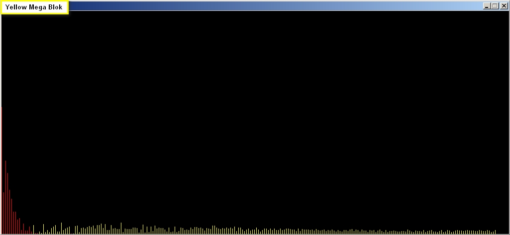
Yellow Mega Blok
Green Mega Blok
When the displayed bars are RED, it indicates that the Red LED is absorbing MORE light than the Yellow LED (and vice versa). Hence this is a "Difference Chart". The Green Mega Blok absorbs more Red Light than the other blocks, therefore producing a big difference between Red LED sensor readings and Yellow Sensor readings.
Here is the list of components required to perform this experiment
//Define the pins for the Red LED Sensor #define Red_LED_Sensor_POS 4 #define Red_LED_Sensor_NEG 5
//Define the pins for the Yellow LED Sensor #define Yellow_LED_Sensor_POS 7 #define Yellow_LED_Sensor_NEG 8
//Define the pin for the RGB LED torch #define RGB_LED_RedPin 9 #define RGB_LED_GreenPin 10 #define RGB_LED_BluePin 11 int intensity=0;
//Define the maximum cycles/time allowed for each LED to capture light long max_darkness=80000;
voidsetup(){ //Setup the RED LED Sensor pinMode(Red_LED_Sensor_POS,OUTPUT); digitalWrite(Red_LED_Sensor_POS,LOW);
//Setup the YELLOW LED Sensor pinMode(Yellow_LED_Sensor_POS,OUTPUT); digitalWrite(Yellow_LED_Sensor_POS,LOW);
//No need to setup the RGB LED Pins
//Turn on Serial Protocol Serial.begin(9600); }
voidloop() {
byte byteRead; // check if data has been sent from the computer: if (Serial.available()) { // read the most recent byte (which will be from 0 to 255): byteRead = Serial.read(); // set the brightness of the LED: analogWrite(RGB_LED_RedPin, byteRead); analogWrite(RGB_LED_GreenPin, byteRead); analogWrite(RGB_LED_BluePin, byteRead);
//Read the amount of Yellow light read_LED('Y', Yellow_LED_Sensor_NEG);
//Read the amount of Red light read_LED('R', Red_LED_Sensor_NEG); } }
void read_LED(char LED_Colour, int LED_Pin){
// Charge the LED by applying voltage in the opposite direction pinMode(LED_Pin,OUTPUT); digitalWrite(LED_Pin,HIGH);
//Read the amount of Light coming into the LED sensor long darkness=0; int lightLevel=0; pinMode(LED_Pin,INPUT); digitalWrite(LED_Pin,LOW);
//This sketch was written by ScottC, but was adapted from a sketch //written by Tom Igoe in 2005
// This example code is in the public domain.
import processing.serial.*;
Serial myPort; // The serial port int xPos = 1; // horizontal position of the graph float YellowVal=0; // The variable to hold the Yellow Sensor Reading float RedVal=0; // The variable to hold the Red Sensor Reading float Diff=0; // The variable to hold the difference between the readings int Switcher=0; // Used to control the flow of the program
voidsetup () { // set the window size: size(1020, 750);
// List all the available serial ports println(Serial.list()); // I use COM13 for my Serial Port - you will need to change this to suit your system myPort = new Serial(this, "COM13", 9600); // don't generate a serialEvent() unless you get a newline character: myPort.bufferUntil('\\n'); // set inital background: background(0); //Send a value to the Arduino to start the feedback mechanism myPort.write(0); } voiddraw () { // everything happens in the serialEvent() }
void serialEvent (Serial myPort) { // get the ASCII string: String inString = myPort.readStringUntil('\\n');
if (inString != null) { // trim off any whitespace: inString = trim(inString);
//The arduino sends 2 sensor readings. The following code //helps to identify which reading is which. if(inString.equals("Y")){ Switcher=0; } elseif (inString.equals("R")){ Switcher=1; } else {
//Convert the String to a float float inByte = float(inString); //Map the reading, so that the chart fits within the window. inByte = map(inByte, 0, 1000, 0, height);
if(Switcher==0){ //Save the reading from the yellow sensor to YellowVal YellowVal=inByte; } else { //Save the reading from the red sensor to RedVal RedVal=inByte; //Calculate the difference between the readings Diff=RedVal-YellowVal;
//If the yellow sensor is greater, plot with a yellow line //If the red sensor reading is greater, plot a red line. if(Diff<=0){ stroke(255,255,0); Diff=abs(Diff); } else { stroke(255,0,0); } // draw the line: line(xPos, height, xPos, height - Diff);
// at the edge of the screen, go back to the beginning: if (xPos > width) { xPos = 0; background(0); //Send a value to the Arduino to change the intensity //of the RGB LED and take another reading myPort.write(xPos); } else { // increment the horizontal position: Increment by more // to get less readings and to make it quicker xPos+=4; if (xPos>0){ //Send a value to the Arduino to change the intensity //of the RGB LED and take another reading myPort.write(xPos/4); } else { myPort.write(xPos); } } } } } }
Have you ever wondered if there was a way to store and retrieve data from a USB stick with an Arduino UNO? Most people choose SD cards to store their project data, but you may be surprised there IS a way! IC Station have a nice little module which allows you store and retrieve your Arduino (or other MCU) project data to a USB stick. I am not too sure why USB storage is not widely used in Arduino projects? These modules are not expensive, they have been around for quite a while, and are relatively simple to use. You do not need any libraries to get them to work, however, I must say that documentation for this module is not that easy to find. This site and this document proved to be very useful in my endevour to get this module working, and I hope my tutorial below will help you get started and bridge some of the information gaps. The...
Add sound or music to your project using the "Grove Serial MP3 Player". An Arduino UNO will be used to control the Grove Serial MP3 player by sending it specific serial commands. The Grove Base Shield allows for the easy connection of Grove sensor modules to an Arduino UNO without the need for a breadboard. A sliding potentiometer, switch and button will be connected to the Base shield along with the Serial MP3 player. A specific function will be assigned to each of the connected sensor modules to provide a useful interface: Sliding Potentiometer – Volume control Button – Next Song Switch – On/Off (toggle) Once the MP3 module is working the way we want, we can then build a simple enclosure for it. Grab a shoe-box, print out your favourite design, and ...


Comments
Post a Comment